1 MBM 1.0/2.0 (TF307)
Contents
1.1 Board Overview
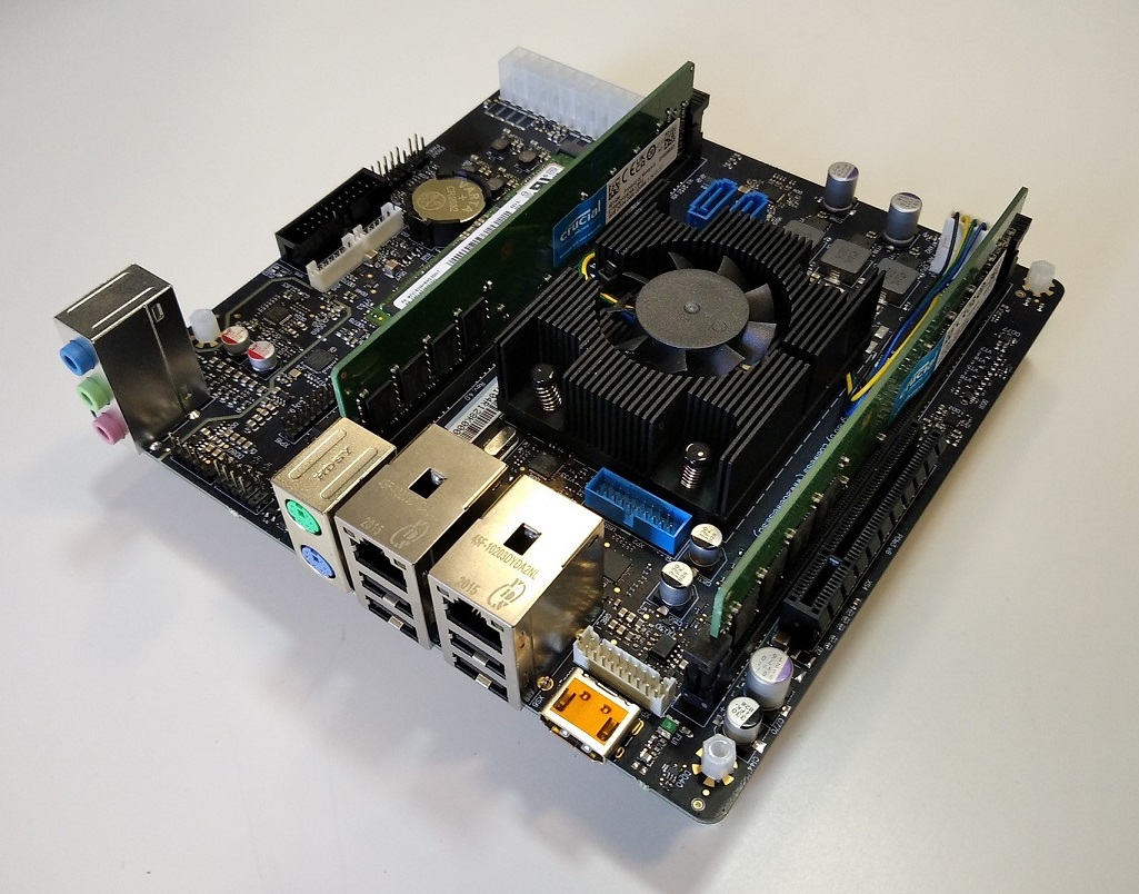
A system board in the mini-ITX form factor. The board’s compact and unified design is suitable for any desktop solution compatible with the mini-ITX form factor.
The figures below shows the MBM 2.0 board (TF307-MB-S-D). The MBM 1.0 board has a similar design and only minor differences.
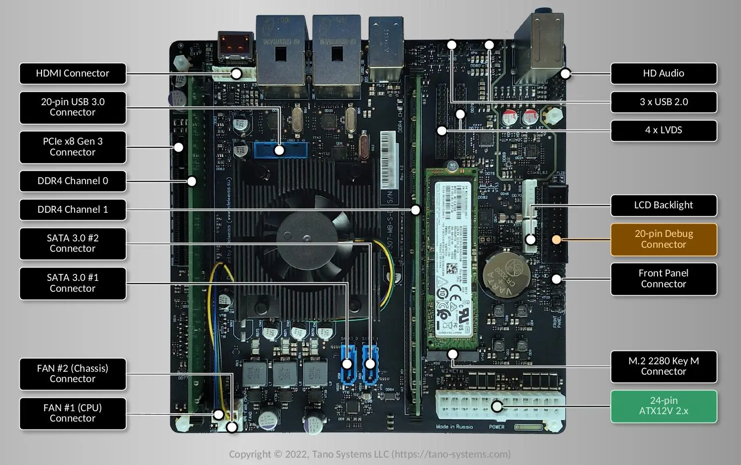
Fig. 1.17 MBM 2.0 (TF307-MB-S-D) Board Top View
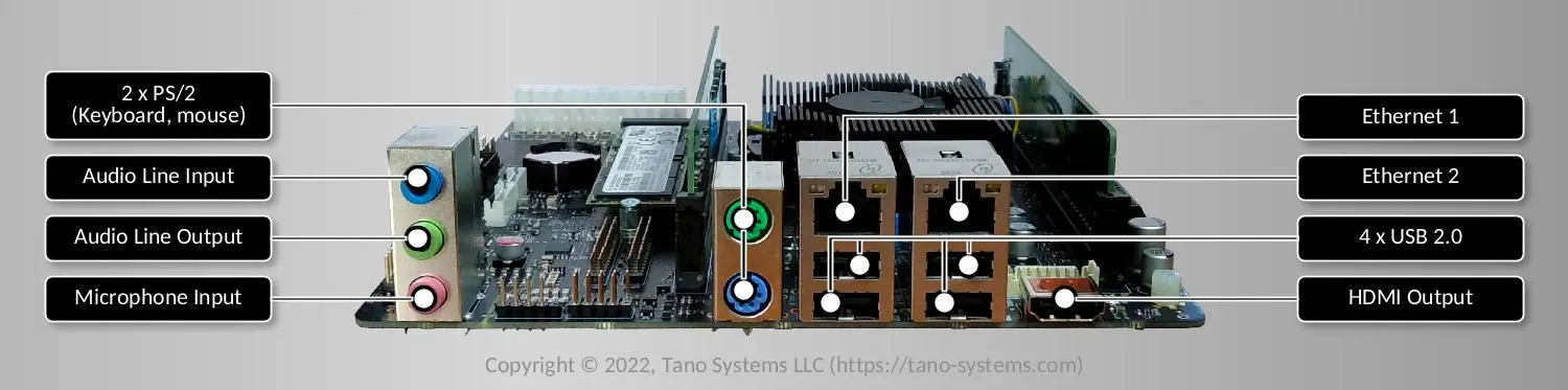
Fig. 1.18 MBM 2.0 (TF307-MB-S-D) Board Front View
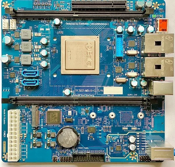
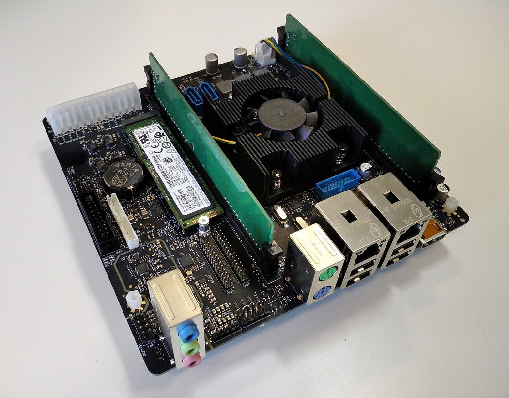
1.1.1 Photos
1.1.2 Specification
Model |
MBM 1.0/2.0 (TF307) |
|---|---|
Processor |
Baikal Electronics BE-M1000
8-core ARM Cortex-A57 64 bits processor,
frequency up to 1.5 GHz
|
Memory |
up to 64 GiB DDR4 2133 (ECC supported)
2 × 288-pin DIMM sockets
|
Audio |
HD audio codec
|
I/O panel connectors |
1 × HDMI output
4 × USB 2.0
2 × PS/2
2 × RJ45 1000BASE-T
1 × Linear audio output
1 × Linear audio input
1 × Microphone input
|
Front panel I/O connectors |
1 × HD audio connector
1 × front panel connector (buttons, LED’s)
2 × USB 3.0
|
Expansion slots |
1 × M.2 M key (PCIe 3.0 x4) for NVME SSD
1 × PCIe 3.0 x8
|
Internal connectors |
2 × SATA 3.0
2 × 4-pin connectors for FAN
1 × LVDS (4 channels)
1 × LCD backlight connector
3 × USB 3.0
1 × 24-pin power
|
Power |
ATX 24 |
Dimensions |
170 mm × 170 mm |
1.2 Build Targets
1.2.1 Machines
Board[1] |
Hardware Revision |
Target YAML[2] |
Machine[3] |
Target Recipe(s)[4] |
Running Media[5] |
Installation Media[6] |
|---|---|---|---|---|---|---|
MBM 1.0 |
TF-307-MB-S-A (Rev 1.0)
TF-307-MB-S-B (Rev 2.0)
TF-307-MB-S-C (Rev 3.0)
|
|
|
|
USB Flash |
– |
MBM 2.0 |
TF-307-MB-S-D (Rev 4.0)
|
|
|
1.2.2 Images
Read-Only Root Filesystem Image |
Recipe[7] |
Supported by Target(s) |
Description |
|---|---|---|---|
|
|
All |
Standard TanoWrt image. |
|
All |
Standard TanoWrt image
and firmware upgrade
image. When building this image,
|
|
|
|
All |
Standard TanoWrt image with Qt5 support. |
|
All |
Standard TanoWrt image with Qt5 support
and firmware upgrade
image. When building this image,
|
1.3 Build
Please read the common information on how to perform a TanoWrt images build and preparing the build environment in section “Building TanoWrt”.
See also
See section Section 1.2.1 to select the required target YAML file (
<target-yml>).See section Section 1.2.2 to select the required root filesystem image recipe (
<target-recipe>).See section Section 1.4 for detailed information about the produced build artifacts.
1.3.1 Examples
1.3.1.1 Build Default Images for MBM 1.0 Board
$ kas build targets/kas/mbm10.yml
1.3.1.2 Build Default Images for MBM 2.0 Board
$ kas build targets/kas/mbm20.yml
1.3.1.3 Build tanowrt-image-full-qt5 Image for MBM 2.0 Board
$ kas build --target tanowrt-image-full-qt5 targets/kas/mbm20.yml
1.4 Produced Build Artifacts
All produced build artifacts are stored in the ~/tanowrt/build/tanowrt-glibc/deploy/images/<MACHINE> directory.
Refer to table Produced Build Artifacts for a description of some common (not all) build artifacts.
Artifact |
Target(s) |
Description |
|---|---|---|
Bootloader |
||
|
All |
GRUB bootloader image |
|
All |
GRUB bootloader initial environment |
|
All |
Startup script for UEFI shell |
|
All |
GRUB bootloader configuration file |
Linux Kernel |
||
|
All |
Linux kernel binary image |
Images |
||
|
All |
Bootable image including all required partitions for booting and running the system. This image is ready to be written to the USB flash drive using the dd utility or similar (see Writing Images). |
|
All |
Root filesystem image (squashfs with LZO compression). |
|
All |
Firmware upgrade image. |
Note
<MACHINE> in the artifacts path and artifacts file names are replaced by the actual
value of the MACHINE BitBake variable for the chosen target.
<rootfs-image> is replaced by the actual read-only rootfs filesystem image name.
For example, below is the complete list of artifacts produced by the
mbm20.yml target build.
[~/tanowrt/build/tanowrt-glibc/deploy/images/mbm20]$ ls -gGh
total 300M
drwxr-xr-x 2   40 May 20 18:10 grub
-rwxr-xr-x 2 2.2K May 20 18:10 grub.cfg
-rw-r--r-- 2 804K May 20 06:13 grub-efi-bootaa64.efi
-rw-r--r-- 2   23 May 20 06:13 grub-efi-bootaa64.efi.version
-rwxr-xr-x 2 1.0K May 20 18:10 grub-efi-grubenv
-rw-r--r-- 2   27 May 20 06:13 grub-efi-startup.nsh
lrwxrwxrwx 2   57 Jul 23 02:07 Image -> Image--5.4.156-tano3.2.12.20.0.0-mbm20-20220722230057.bin
-rw-r--r-- 2  17M Jul 23 02:07 Image--5.4.156-tano3.2.12.20.0.0-mbm20-20220722230057.bin
-rw-r--r-- 2  21M Jul 23 02:07 Image-5.4.156-tano3.2.12.20.0.0-mbm20.ext4
lrwxrwxrwx 2   57 Jul 23 02:07 Image-mbm20.bin -> Image--5.4.156-tano3.2.12.20.0.0-mbm20-20220722230057.bin
-rw-r--r-- 2  21M Jul 23 02:07 Image-mbm20.ext4
-rw-r--r-- 2  13M Jul 23 02:07 modules--5.4.156-tano3.2.12.20.0.0-mbm20-20220722230057.tgz
lrwxrwxrwx 2   59 Jul 23 02:07 modules-mbm20.tgz -> modules--5.4.156-tano3.2.12.20.0.0-mbm20-20220722230057.tgz
-rw-r--r-- 2 4.8K Jul 23 02:09 tanowrt-image-full.env
-rw-r--r-- 2 1.9K Jul 23 02:09 tanowrt-image-full-image-baikal-m-swu-a-b.wks
-rw-r--r-- 2  85K Jul 23 02:09 tanowrt-image-full-mbm20-20220722230057.rootfs.manifest
-rw-r--r-- 2  44M Jul 23 02:09 tanowrt-image-full-mbm20-20220722230057.rootfs.squashfs-lzo
-rw-r--r-- 2   24 Jul 23 02:10 tanowrt-image-full-mbm20-20220722230057.rootfs.version
-rw-r--r-- 2 915M Jul 23 02:09 tanowrt-image-full-mbm20-20220722230057.rootfs.wic
-rw-r--r-- 2 336K Jul 23 02:09 tanowrt-image-full-mbm20-20220722230057.testdata.json
lrwxrwxrwx 2   55 Jul 23 02:09 tanowrt-image-full-mbm20.manifest -> tanowrt-image-full-mbm20-20220722230057.rootfs.manifest
lrwxrwxrwx 2   59 Jul 23 02:09 tanowrt-image-full-mbm20.squashfs-lzo -> tanowrt-image-full-mbm20-20220722230057.rootfs.squashfs-lzo
lrwxrwxrwx 2   53 Jul 23 02:09 tanowrt-image-full-mbm20.testdata.json -> tanowrt-image-full-mbm20-20220722230057.testdata.json
lrwxrwxrwx 2   54 Jul 23 02:10 tanowrt-image-full-mbm20.version -> tanowrt-image-full-mbm20-20220722230057.rootfs.version
lrwxrwxrwx 2   50 Jul 23 02:09 tanowrt-image-full-mbm20.wic -> tanowrt-image-full-mbm20-20220722230057.rootfs.wic
-rw-r--r-- 2  66M Jul 23 02:10 tanowrt-image-full-swu-mbm20-20220722230057.swu
lrwxrwxrwx 2   47 Jul 23 02:10 tanowrt-image-full-swu-mbm20.swu -> tanowrt-image-full-swu-mbm20-20220722230057.swu
1.5 Writing Images
1.5.1 Wriging Image to USB Flash Drive
No special information about writing images to USB flash drive for described boards. See common instructions in Writing Images to SD Card or USB Flash Drive section.
Examples
Writing bootable card image for the mbm20.yml target to the USB flash drive
/dev/sdc:
$ dd if=tanowrt-image-full-mbm20.wic of=/dev/sdc
1.6 Booting and Running
To successfully run TanoWrt on MBM 1.0/2.0 boards UEFI firmware from Baikal-M SDK 5.2 20210608 or higher is required. Follow the instructions from the SDK to update the UEFI firmware on MBM 1.0/2.0 board.
1.6.1 Booting from USB Flash Drive
Power off board.
Insert prepared USB flash drive with TanoWrt to any USB 2.0 or 3.0 port (see section Board Overview).
Power on board.
Press ESC to enter UEFI setup utility.
Select Boot Manager in menu and press ENTER.
Select your USB flash drive in boot manager menu and press ENTER. TanoWrt will be booting from selected USB flash drive.
When the system boots, log in using the default credentials.
1.7 Default Network Configuration
By default, network ports Ethernet 1 (eth0) and Ethernet 2 (eth1)
are joined into a bridge (br-lan interface) with the RSTP
protocol enabled. Bridge (br-lan) configured with static IP address
192.168.0.1/24 with enabled DHCP server.
Ethernet ports 1 (eth0) and 2 (eth1) have enabled LLDP by default.
1.8 Web User Interface
The WebUI can be accessed via Ethernet port or USB network connection through HTTP(s) protocol. You must see something like this in browser after you logged in:
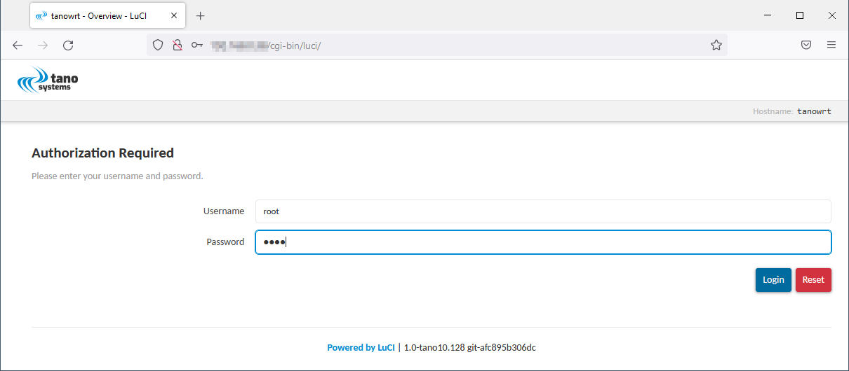
Fig. 1.22 LuCI WebUI Login Page
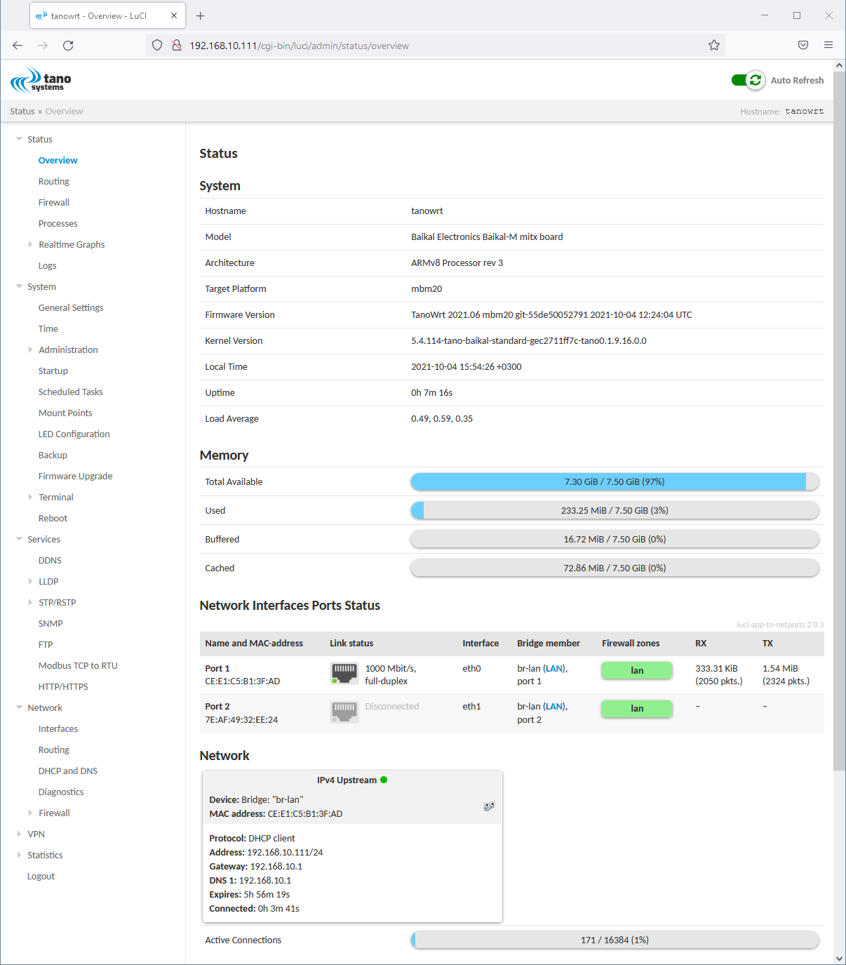
Fig. 1.23 LuCI WebUI Overview Page
1.9 Firmware Upgrade
No special information about firmware upgrade.
Use produced .swu artifact for upgrading running system.
See also
See common instructions in Firmware Upgrade section.